Method

Graph Based Road Estimation with Sparse 3D Points from Sparse ELAS [st] [GRES3D+SELAS]


Submitted on 6 Dec. 2014 00:00 by
Patrick Shinzato (Mobile Robotic Laboratory, ICMC - USP)

Running time:110 ms
Environment:4 core @ 2.8 Ghz (C/C++)

Method Description:
Its a novel robust road estimation method that makes use of sparse 3D points projected in a screen plane. These 3D points are (u,v,d) points generated after perform a modified version of the disparity algorithm ELAS. The main idea of the road estimation is to calculate a obstacle confidence degree for each point and then estimates the road area using a polar range histogram. Its free of several assumptions as flat surface and minimum height. Furthermore, its free of sensor.
Parameters:
ELAS parameters are default except by:
disp_min = 0
disp_max = 96
ipol_gap_width = 15000
postprocess_only_left = true
filter_adaptive_mean = false
filter_median = false

Road estimation parameters are:
lambda = 5
theta = 11.7
hist_precision = 5.0
Latex Bibtex:
@phdthesis{Shinzato2015,
author = {Patrick Yuri Shinzato},
title = {Estimation of obstacles and road area with sparse 3D points},
school = {Institute of Mathematics and Computer Science (ICMC) / University of Sao Paulo (USP)},
year = 2015,
note = {http://www.teses.usp.br/teses/disponiveis/55/55134/tde-07082015-100709/en.php}
}

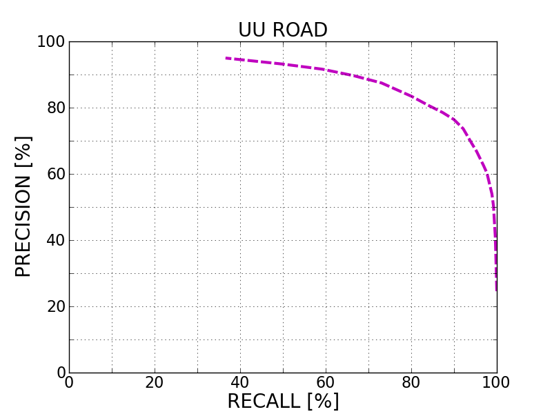
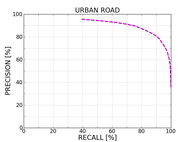
Evaluation in Bird's Eye View


Benchmark MaxF AP PRE REC FPR FNR
UM_ROAD 83.69 % 84.61 % 78.31 % 89.88 % 11.35 % 10.12 %
UMM_ROAD 87.57 % 90.52 % 85.92 % 89.28 % 16.08 % 10.72 %
UU_ROAD 82.70 % 83.95 % 78.54 % 87.32 % 7.77 % 12.68 %
URBAN_ROAD 85.09 % 86.86 % 82.27 % 88.10 % 10.46 % 11.90 %
This table as LaTeX

Behavior Evaluation


Benchmark PRE-20 F1-20 HR-20 PRE-30 F1-30 HR-30 PRE-40 F1-40 HR-40
This table as LaTeX

Road/Lane Detection

The following plots show precision/recall curves for the bird's eye view evaluation.


This figure as: png eps pdf

This figure as: png eps pdf

This figure as: png eps pdf

This figure as: png eps pdf

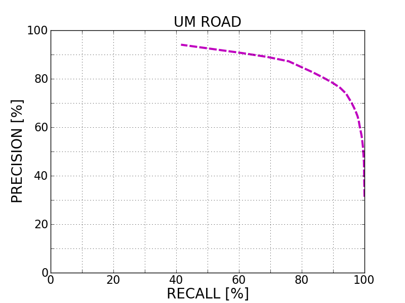
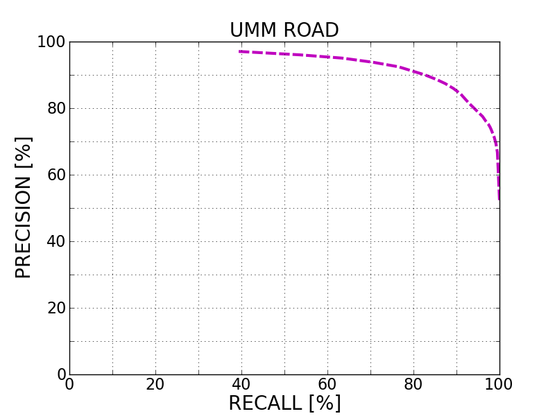
Distance-dependent Behavior Evaluation

The following plots show the F1 score/Precision/Hitrate with respect to the longitudinal distance which has been used for evaluation.


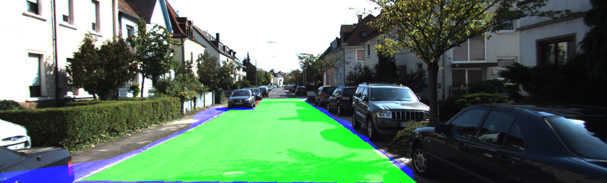
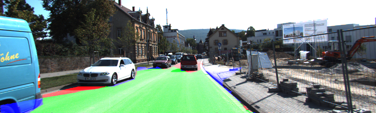
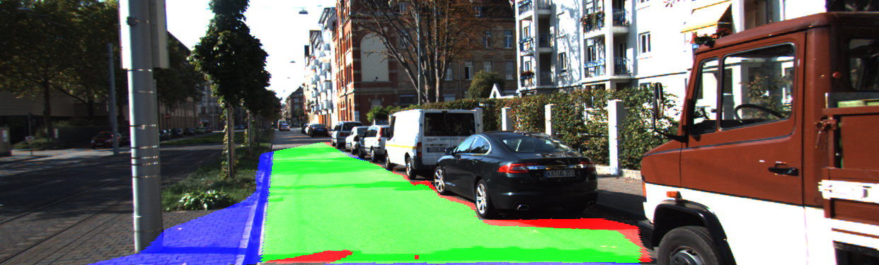
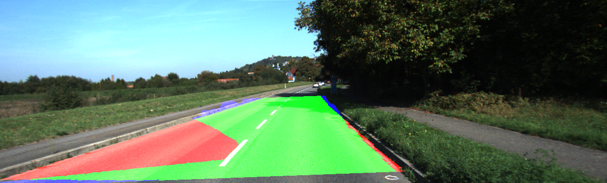
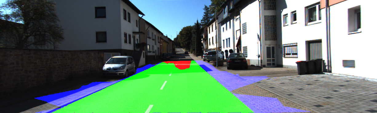
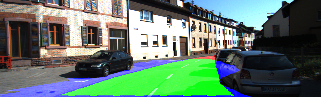
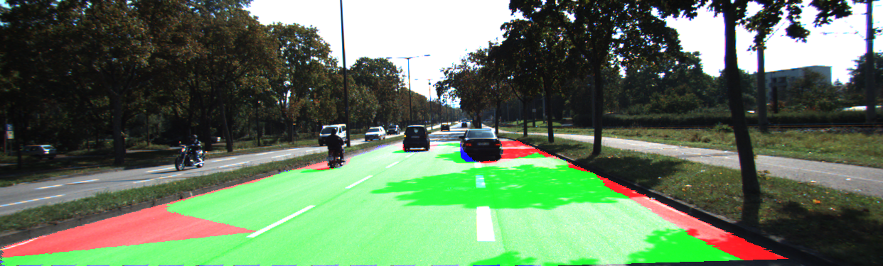
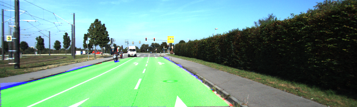
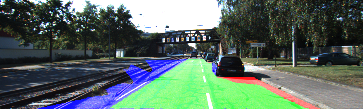
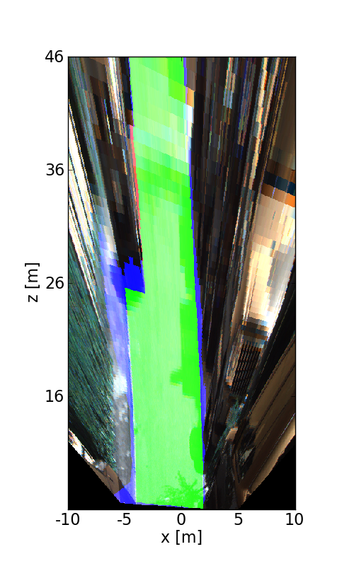
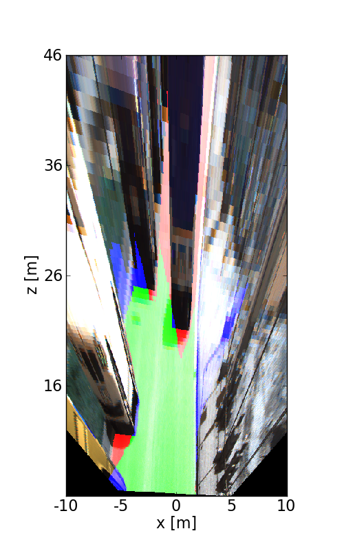
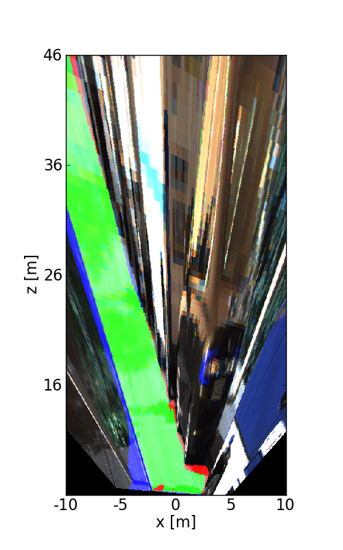
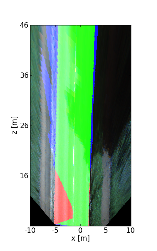
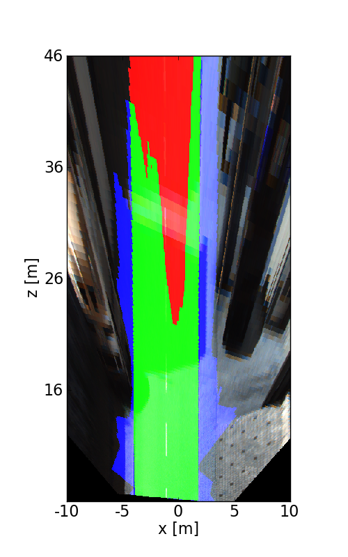
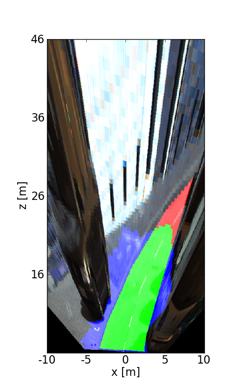
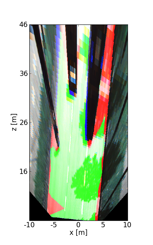
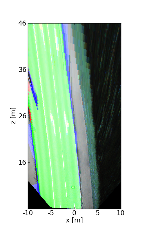
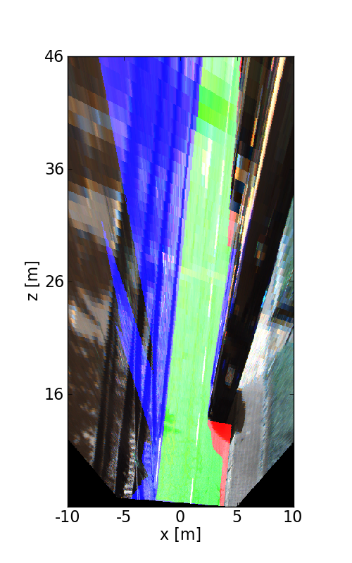
Visualization of Results

The following images illustrate the performance of the method qualitatively on a couple of test images. We first show results in the perspective image, followed by evaluation in bird's eye view. Here, red denotes false negatives, blue areas correspond to false positives and green represents true positives.


This figure as: png

This figure as: png

This figure as: png

This figure as: png

This figure as: png

This figure as: png

This figure as: png

This figure as: png

This figure as: png

This figure as: png

This figure as: png

This figure as: png

This figure as: png

This figure as: png

This figure as: png

This figure as: png

This figure as: png

This figure as: png


eXTReMe Tracker